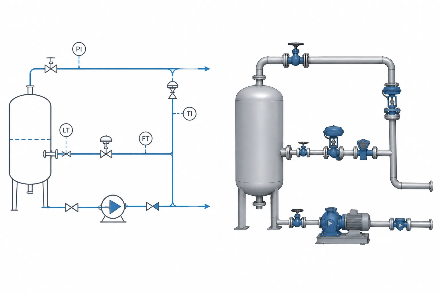
• P&ID Symbols vs. 3D Piping Components: How to Translate Process Intent into CAD

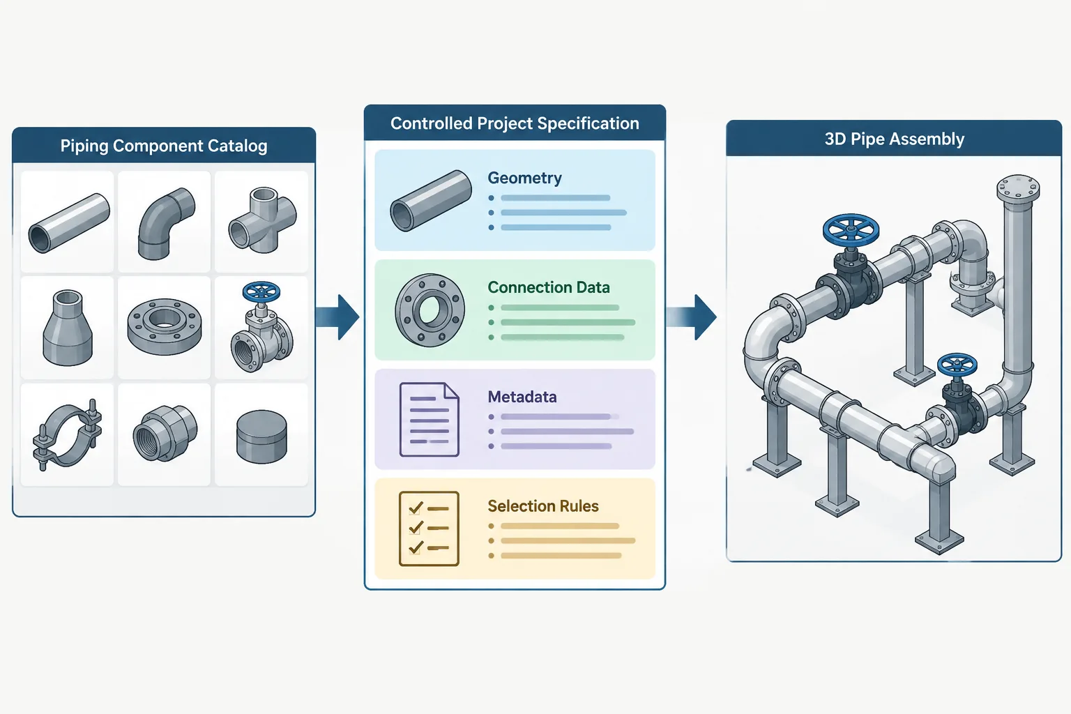
    P&ID Symbols vs. 3D Piping Components: How to Translate Process Intent into CAD

  • Reducing Tee vs. Equal Tee and Reducer: A Practical Piping Layout Comparison

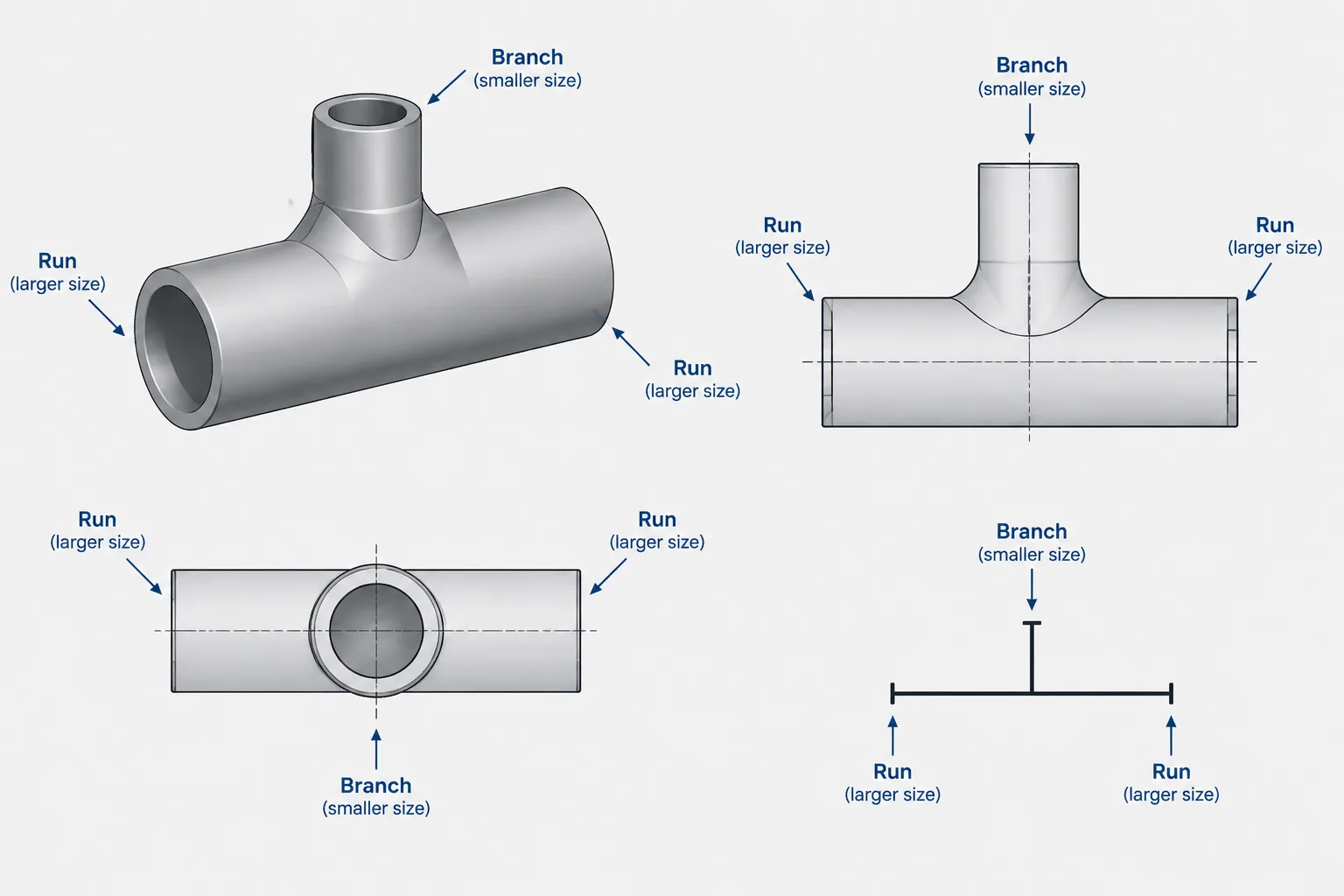
    Reducing Tee vs. Equal Tee and Reducer: A Practical Piping Layout Comparison

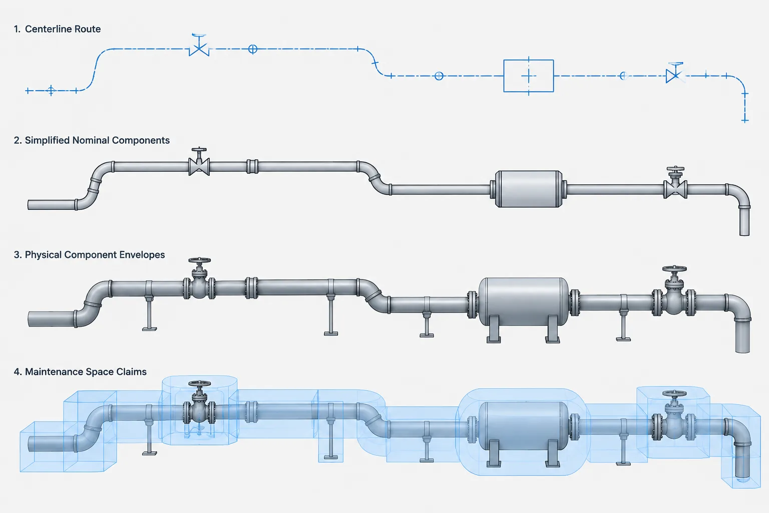
  • Pipe Centerline Spacing in CAD: How to Account for Insulation, Flanges, Valves, and Access

    Pipe Centerline Spacing in CAD: How to Account for Insulation, Flanges, Valves, and Access

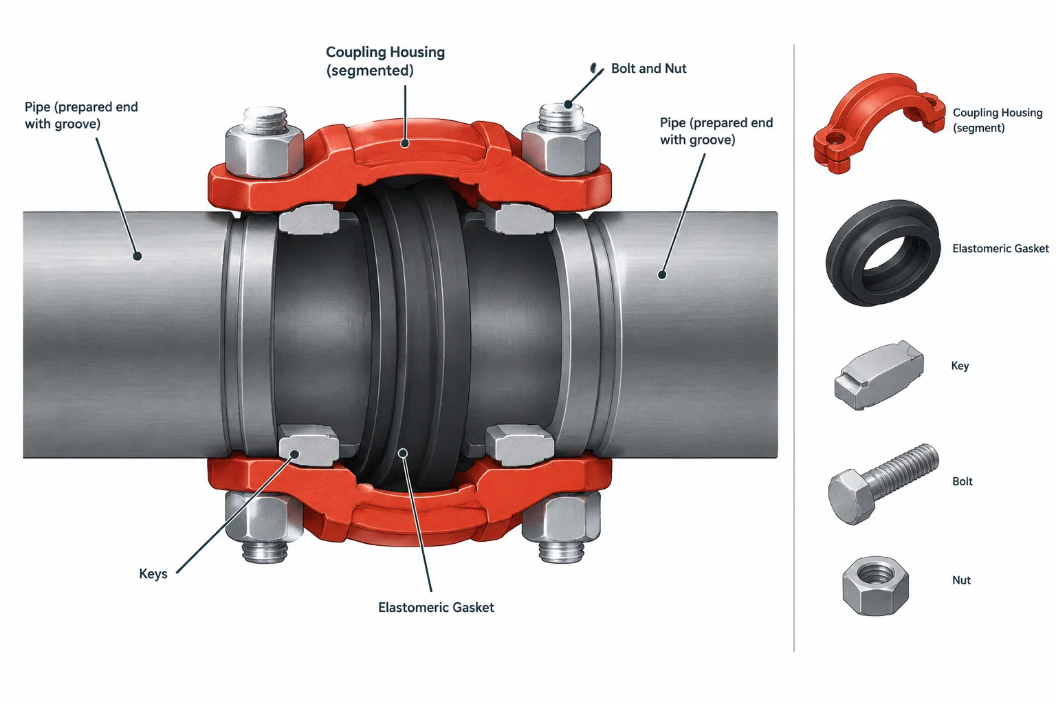
  • Grooved Pipe Connections in CAD: Couplings, End Gaps, and Cut-Length Control

    Grooved Pipe Connections in CAD: Couplings, End Gaps, and Cut-Length Control

  • Valve Operator Extensions and Chain Wheels in Piping CAD: A Practical Layout Guide

    Valve Operator Extensions and Chain Wheels in Piping CAD: A Practical Layout Guide

  • Lap Joint Flanges and Stub Ends in Piping CAD: Assembly, Rotation, and Dimension Control

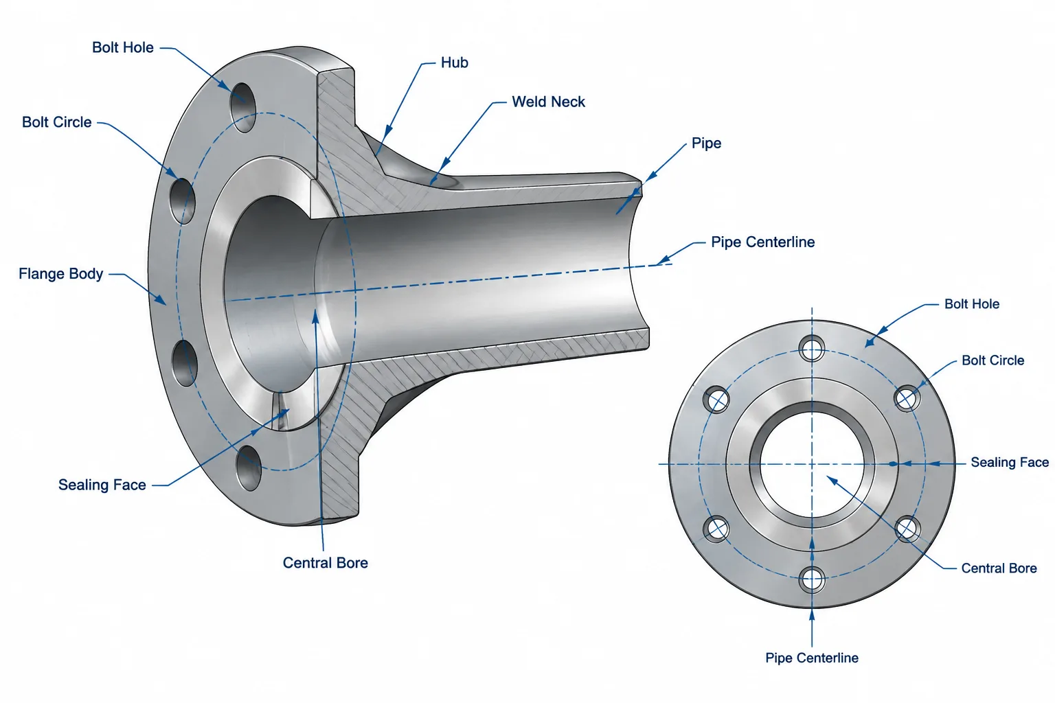
    Lap Joint Flanges and Stub Ends in Piping CAD: Assembly, Rotation, and Dimension Control

  • Pipe Unions vs. Couplings in Piping CAD: Assembly, Maintenance, and Cut-Length Control

    Pipe Unions vs. Couplings in Piping CAD: Assembly, Maintenance, and Cut-Length Control

  • Orifice Flanges and Meter Runs in Piping CAD: A Practical Layout and Detailing Guide

    Orifice Flanges and Meter Runs in Piping CAD: A Practical Layout and Detailing Guide

  • Swage Nipples vs. Pipe Reducers: Selection, Connections, and CAD Detailing

    Swage Nipples vs. Pipe Reducers: Selection, Connections, and CAD Detailing